
Absolute
Starts at vacuum = 0. Atmosphere sits near 1 bar. This is what the sensor physically measures.
0 → 4 bar abs
V1.1 · 52mm
How will this gauge get its sensor data?
Important if you plan to use the gauge in a vehicle: Revvgauge is an auxiliary information display and is not intended to replace or disable any original vehicle safety system, required tell-tale, warning indicator, or federally required vehicle instrument. Installation must not interfere with airbags, required lighting, driver visibility, or other safety equipment. For off-road use only.
Inside you should find your Revvgauge and the standard loom, plus any sensors or extra cables included with your order.
Inside you should find your Revvgauge, the standard loom, and any analog sensors included with your order.
Inside you should find your Revvgauge and the OBD2 cable.
Inside you should find your Revvgauge and the standard loom.
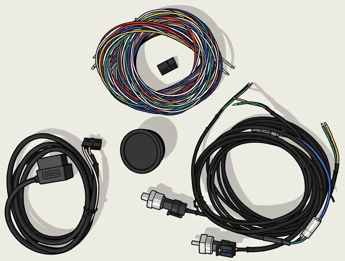
Are you using the standard loom or the OBD2 cable?
The OBD2 cable arrives with GND, VIN, and the CAN pins already seated — you can skip inserting those wires.
Every loom wire ends in a pre-crimped Micro-Fit terminal. These push into the back of the 16-pin Molex housing until they click and lock.
Hold the wire near the crimp and insert the metal terminal thin end first into the correct cavity. The terminal only seats one way — locking tabs must line up with the cavity. If it feels stuck, stop and check the orientation rather than forcing it.
Push firmly until you feel/hear a click. Give the wire a gentle tug to confirm it’s locked. Use this same method for power, ground, and every other input or output cable.
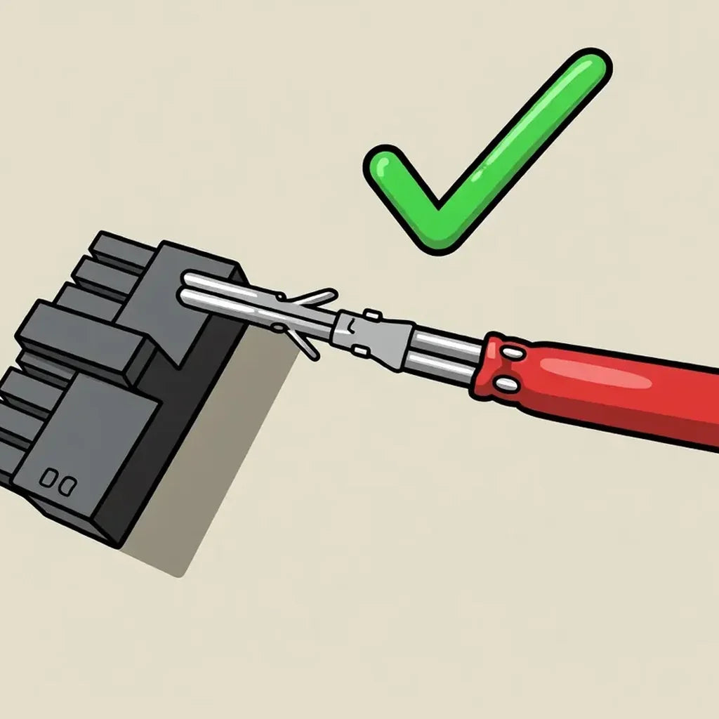
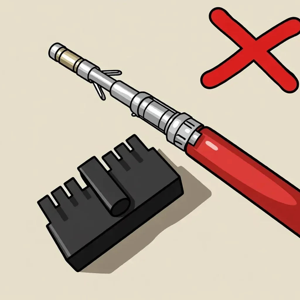
Choose which cables your gauge will need and insert them now using the method above. If you’re on the standard loom, start with power and ground. If you’re using the OBD2 cable, GND, VIN (power), and the CAN pins are already populated — you can skip those and only insert any other cables you need. The lighting input is also pre-populated with a short (~20 cm) cable; extend it with your standard loom cable or another wire to the desired location. Tap the pin layout image to view it full screen for reference.
Insert power, ground, and the analog input wires you’ll use. Leave unused analog pins empty. Tap the pin layout image to view it full screen for reference.
Start with power and ground from the standard loom, then insert CAN H and CAN L. Tap the pin layout image to view it full screen for reference.
Power, ground, and CAN are already populated on the OBD2 cable. Use the pin layout below if you want to confirm those seats.
Insert the 12–24V power cable — VIN, red (RD), 18 AWG — into pin 13 on the 16-pin Molex.
Pay close attention when inserting: the pin must go in thin-end first, in this orientation.
Next, insert the GND cable — black (BK), 18 AWG — into pin 14. It splits into two so you can more easily run a ground to your analog sensors and a separate ground for the gauge power supply.
If you’re using the OBD2 cable, GND, VIN (power), and the CAN pins are already populated — skip those. The lighting input is also pre-populated with a short (~20 cm) cable; extend it with your standard loom cable or another wire to the desired location. Insert any other pins you need using the method from the previous step.
GND, VIN (power), and the CAN pins are already populated on the OBD2 cable.
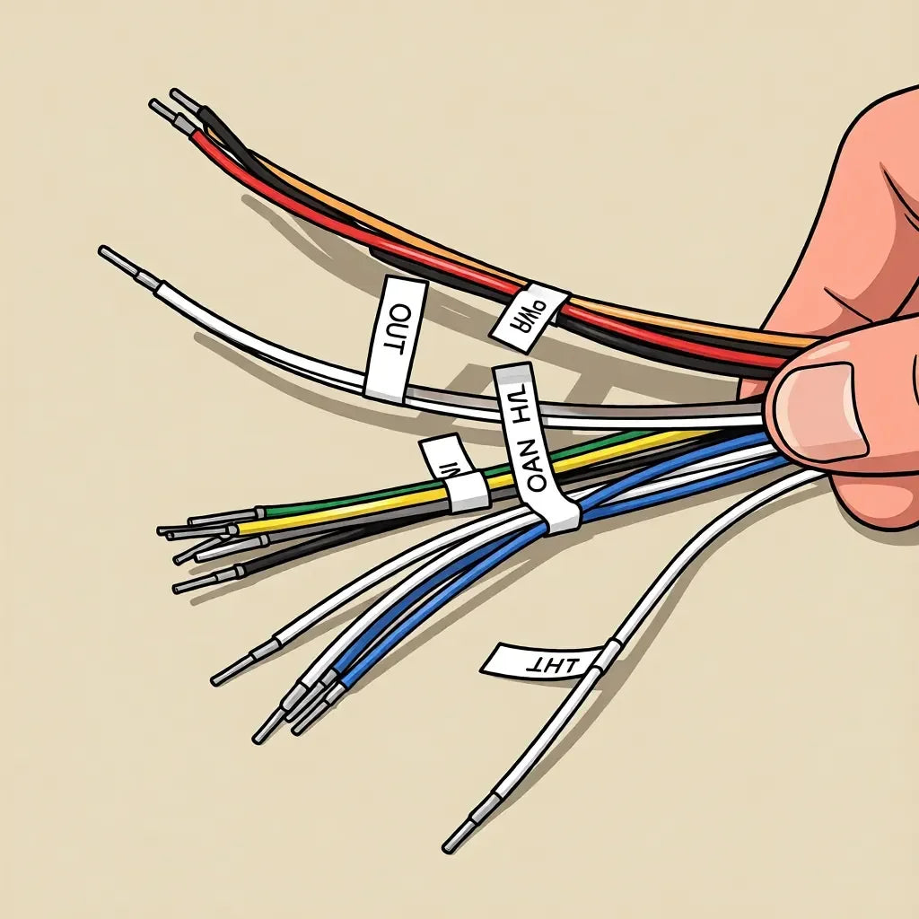
Check pin numbers and connector orientation before inserting any wires. Confirm you’re looking at the correct side of the connector and that each terminal goes into the matching numbered cavity.
Insert the red and black wires from the standard loom power group into the Molex.
Leave the orange wire out for now — it is only used to power any 5V sensors.
Ignore +5V — orange (OG), pin 15 — until you connect a 5V sensor.
Insert the analog sensor wires into the matching Molex pins for your planned inputs. Keep sensor grounds tidy with the split GND lead from pin 14.
It’s recommended not to attach the actual sensor yet — wait until step 7 (Wire in your device).
If you’re using linear 5V sensors, also insert +5V — orange (OG) — into pin 15 so those sensors are powered.
Insert the CAN high and CAN low wires into the Molex. There are two cavities for each so you can daisy-chain CAN if needed — confirm polarity before seating.
Insert the controllable output wires into the assigned output pins. Leave unused output pins empty until you need them.
Insert the LIGHT wire — white/grey (WHGY) — into pin 16. The other end connects to your vehicle’s illumination / headlight circuit so Revvgauge can switch between light and dark themes when the lights turn on or off.
You’re ready to move to where you’ll mount the gauge — car, tiny home, caravan, or elsewhere. Roughly route the wiring from the power source to the mount location.
Route the OBD2 cable from the vehicle’s OBD2 port to where you’ll mount the gauge.
With the loom prepared and wires roughly routed, you can begin wiring the gauge into your vehicle or setup. Open the sections that apply to your install.
With the loom prepared and wires roughly routed, wire power and your analog sensors into the vehicle or setup.
With the loom prepared and wires roughly routed, wire power and CAN H / CAN L into your vehicle or ECU bus.
Plug the OBD2 connector into the vehicle’s OBD2 port. On most cars this is under the driver’s footwell, near the kick panel or steering column. Power and CAN come from that port — no Molex pin work is required.
It’s normal for the gauge to boot even with the car off — the OBD2 port is connected directly to battery. Once you load a gauge onto the device, you can set it to auto sleep. If you follow the setup in the app, this is configured automatically for OBD2.
Connect VIN to a fused 12–24V supply and GND to chassis / battery negative.
In a vehicle, use an ignition-switched circuit so the gauge is powered when the vehicle is on — not a permanent battery feed (unless you want it always on).
OBD2 installs can skip this — power and ground come from the OBD2 port.
Run each sensor signal wire to the matching analog input. Use a shared sensor ground from the split GND (pin 14), and power linear 5V sensors from +5V (pin 15).
For NTC temperature sensors, connect signal to an AIN and the other leg to GND. For linear 0–5V sensors, connect signal to AIN, power to +5V, and ground to GND.
All Revvgauge–issued sensor looms follow the same colours:
If you’re using all 6 inputs, plan how you’ll manage up to 6 ground wires and 6 +5V wires from the sensors — a bus bar or similar distribution block helps a lot. For 1–3 sensors, you can typically crimp the sensor grounds together onto the GND lead, and the sensor +5V wires together onto the +5V lead.
Connect CAN H and CAN L to your vehicle or ECU CAN bus. Keep polarity correct — white is CAN H, blue is CAN L. Pins 5/8 and 6/7 are paired so you can daisy-chain if needed.
When designing the gauge face in the app, you can enable the built-in 120 Ω termination if you need it — no need to terminate the bus manually.
These are low-side outputs. Connect the ground of the device you wish to toggle on and off here — for example a buzzer, LED, or relay — and power the device from a suitable supply.
Do not exceed 1W at 12V.
Leave unused outputs disconnected.
Connect the LIGHT wire to your vehicle’s illumination or headlight circuit so the gauge can switch themes when the lights turn on or off.
Plug the OBD2 connector into the vehicle’s OBD2 port. On most cars this is under the driver’s footwell, near the kick panel or steering column.
It’s normal for the gauge to boot even with the car off — the OBD2 port is connected directly to battery. Once you load a gauge onto the device, you can set it to auto sleep. If you follow the setup in the app, this is configured automatically for OBD2.
Use the locking ring provided where possible to secure the gauge in your chosen location.
If you can’t use the locking ring — for example in a gauge pod — wrap some electrical tape around the body to increase the diameter until it’s a tight fit.
The gauge uses an M52×2 thread. We’ve also provided the CAD files if you want to create a custom mount.
Download REVV Editor, then follow the in-app instructions to connect your gauge, load a layout, and finish setup.
Custom CAN
Revv uses bit-style definitions rather than byte-style. Use this simple calculator to take your CAN protocol’s byte definition and convert it into Revv’s bit style.
Legal
Important — Intended use
The REVVGAUGE Gauge Unit V1.0 is an aftermarket general-purpose instrumentation accessory for non-road and off-grid applications. It is intended for uses such as off-grid living, recreational and competition off-road vehicles, agricultural and industrial equipment, caravans, and similar 12–24 V systems.
It is not intended, approved, or warranted for use as a primary road-legal vehicle instrument cluster, or for any application where applicable road vehicle standards, registration rules, or roadworthiness laws require OEM or ADR-/FVMSS-compliant instrumentation.
By purchasing, installing, or using the Product, you acknowledge and agree that:
Our goods come with guarantees that cannot be excluded under the Australian Consumer Law. You are entitled to a replacement or refund for a major failure and compensation for any other reasonably foreseeable loss or damage. You are also entitled to have the goods repaired or replaced if the goods fail to be of acceptable quality and the failure does not amount to a major failure.
Nothing in these Terms excludes, restricts or modifies any consumer guarantee, right or remedy conferred on you by the Australian Consumer Law or any other applicable law that cannot be excluded, restricted or modified by agreement.
1.1 These Terms and Conditions (Terms) apply to the sale and use of the REVVGAUGE Gauge Unit V1.0 by REVVGAUGE PTY LTD, trading as Revv Gauge (Revv Gauge, we, us, our).
1.2 By placing an order, completing a purchase, installing, configuring, or using the Product, you (you, Purchaser, Customer) agree to be bound by these Terms.
1.3 If you do not agree to these Terms, you must not purchase, install, or use the Product.
1.4 These Terms should be read together with the separate REVVGAUGE Gauge Unit V1.0 Product Warranty (Warranty). Where there is any inconsistency between these Terms and the Warranty in respect of warranty remedies, the Warranty prevails for that subject matter, subject always to the Australian Consumer Law.
2.1 The Product is a general-purpose multifunction 52 mm programmable digital gauge (Model RVG-52), supplied as a complete assembled unit together with any Revv Gauge accessories included at the time of purchase (such as a wiring loom and mounting hardware, if supplied).
2.2 The Product is intended as a configurable information display and data interface for applications such as off-grid homes, off-road vehicles, caravans, industrial equipment, and similar 12–24 V systems. Exact software features may vary by firmware version.
2.3 V1.0 interface note: Connector pins 3 and 4 are additional analog inputs (AIN5 and AIN6). This revision does not include a K-type thermocouple interface. Connecting a thermocouple directly to pins 3 or 4 is not supported and may damage the unit.
2.4 Separately purchased sensors, third-party components, and accessories not included with the Product are not covered by these Terms except as expressly stated at the time of purchase.
3.1 The Product is designed and sold for non-road and off-grid applications as described in these Terms.
3.2 Without limiting clause 3.1, the Product is intended for use as a supplementary instrumentation display in off-grid homes, caravans, off-road vehicles, motorsport and competition vehicles, agricultural machinery, industrial equipment, and similar non-road or stationary applications operating from a nominal 12 V to 24 V DC supply.
3.3 The Product is not intended for:
3.4 The Product is an informational accessory. Readings, alerts, outputs, and displayed values may be incomplete, delayed, inaccurate, or unavailable due to sensor fault, wiring fault, configuration error, electrical noise, CAN bus conditions, firmware behaviour, or other causes. You must not rely solely on the Product for safety-critical decisions, system protection, or legal compliance.
3.5 You are solely responsible for verifying that any installation and use of the Product is lawful in your jurisdiction, including any applicable registration, roadworthiness, electrical, building, or instrumentation requirements.
4.1 You must operate the Product only within the published specifications, including without limitation:
| Parameter | Specification |
|---|---|
| Supply voltage (VIN) | 12 V to 24 V nominal (operate within published limits) |
| Gauge 5 V output | 5 V, 200 mA maximum continuous |
| Analog inputs | AIN1–AIN6; 0 V to 5 V linear, or NTC (100 Ω to 50 kΩ) |
| CAN bus | CAN H / CAN L; 10 kbit/s to 1 Mbit/s |
| Digital outputs | Open-drain low-side; 1 W maximum per output @ 12 V |
| Lighting input | Headlamp / dimmer sense input (where used) |
| Operating temperature | –40 °C to +85 °C |
4.2 Operating the Product outside the specified supply voltage, current, temperature, or interface ratings may cause permanent damage and may void the Warranty to the maximum extent permitted by law.
4.3 Absolute maximum and transient conditions described in design documentation are design limits, not an invitation to operate at those extremes in normal use.
5.1 Revv Gauge recommends that the Product be installed by a qualified electrician or technician familiar with 12–24 V DC electrical systems.
5.2 You must:
5.3 Incorrect installation, reverse polarity (beyond protected limits), overcurrent, unsupported sensors, incorrect CAN wiring, or modification of the Product may cause damage to the Product, the host system, or other equipment, for which you accept responsibility to the maximum extent permitted by law.
6.1 An order placed through our website or authorised sales channel constitutes an offer to purchase. We may accept or reject an order at our discretion.
6.2 Prices are as displayed at the time of order unless otherwise agreed in writing. We may correct obvious pricing errors.
6.3 Title in the Product passes to you on receipt of cleared payment in full. Risk in the Product passes on delivery to you or your nominated carrier, unless otherwise required by law.
6.4 You are only entitled to Warranty benefits after all amounts owing in respect of the Product have been paid.
7.1 Delivery timeframes are estimates only and are not guaranteed.
7.2 You must provide accurate delivery details. We are not responsible for delays or loss caused by incorrect address information, refusal of delivery, or carrier events beyond our reasonable control.
7.3 International orders may be subject to customs duties, taxes, and import restrictions, which are your responsibility unless expressly stated otherwise.
8.1 Nothing in these Terms limits your rights under the Australian Consumer Law.
8.2 Change-of-mind returns, if offered, are at our discretion and may be subject to conditions published at the time of sale (including return shipping and restocking, where lawful).
8.3 Faulty goods claims are handled in accordance with the Australian Consumer Law and, where applicable, the Warranty.
9.1 The Product is supplied with a separate twelve (12) month limited Warranty against defects in materials and workmanship, subject to the exclusions and claim procedures set out in that Warranty.
9.2 Without limiting the Warranty, coverage may be declined where damage or failure results from misuse, incorrect installation, operation outside specifications, unsupported connections, unauthorised modification, or use contrary to these Terms (including use other than the intended use described in clause 3), to the maximum extent permitted by law.
10.1 Firmware and software supplied with the Product are licensed, not sold. You receive a limited, non-exclusive, non-transferable licence to use the software solely with the Product.
10.2 You must not reverse engineer, decompile, or modify the firmware except to the extent expressly permitted by law.
10.3 We may provide firmware updates from time to time. Updates may change features, fix defects, or alter behaviour. You are responsible for applying updates in accordance with our instructions. We do not guarantee uninterrupted or error-free operation.
11.1 All intellectual property in the Product, documentation, firmware, branding, designs, and related materials remains owned by Revv Gauge or its licensors.
11.2 Third-party components and open-source software included in the Product remain subject to their original licences and terms.
12.1 To the maximum extent permitted by law, Revv Gauge is not liable for:
12.2 To the maximum extent permitted by law, our aggregate liability arising out of or in connection with the Product or these Terms is limited to the amount you paid for the Product giving rise to the claim, or, where the Australian Consumer Law requires, to repairing or replacing the Product or paying the cost of repair or replacement.
12.3 Where the Australian Consumer Law applies and liability cannot be excluded, our liability for a breach of a consumer guarantee is limited, to the extent permitted, to one or more of: replacement of the goods; repair of the goods; payment of the cost of replacing the goods; or payment of the cost of having the goods repaired.
13.1 To the maximum extent permitted by law, you indemnify Revv Gauge against claims, losses, damages, costs, and expenses (including reasonable legal fees) arising out of or in connection with:
except to the extent caused by our negligence or breach of a non-excludable consumer guarantee.
14.1 If you acquired the Product for the purpose of resupply, the Warranty may not apply as stated in the Warranty document.
14.2 Sale of the Product via an online auction or unauthorised reseller may affect Warranty eligibility, as Revv Gauge has no control over storage, handling, quality, or safety of Products sold through such channels.
15.1 Revv Gauge is not liable for delay or failure to perform caused by events beyond our reasonable control, including acts of God, war, riots, strikes, epidemic, fire, flood, storm, changes in law or public policy, terrorism, supply-chain disruption, or carrier failure.
16.1 If you provide personal information when purchasing or contacting support, we will handle it in accordance with our privacy practices as published on https://revvgauge.com (or as otherwise notified to you).
17.1 We may update these Terms from time to time by publishing a revised version. The Terms in force at the time of your purchase apply to that purchase, unless a change is required by law.
17.2 Agents, officers, employees, distributors, and resellers are not authorised to vary these Terms unless agreed by Revv Gauge in writing.
18.1 If any provision of these Terms is illegal, unenforceable, or invalid, that provision is to be read down or severed to the minimum extent necessary, and the remaining provisions continue in full force.
19.1 These Terms are governed by the laws of Australia (and, where applicable, the State or Territory in which REVVGAUGE PTY LTD principally carries on business). The courts of that jurisdiction have non-exclusive jurisdiction, subject to any non-excludable consumer rights in your place of residence.
Revv Gauge
Email: support@revvgauge.com
Website: https://revvgauge.com
For warranty claims, follow the claim procedure in the Product Warranty and contact support@revvgauge.com.
Copyright © 2026 Revv Gauge. All rights reserved.
Sensors
The REVV Boost Sensor measures absolute pressure, so it needs a quick zero calibration after install. This page explains why, what that means for your reading range, and how to dial it in.
Absolute pressure is measured from a perfect vacuum — not from the air around you. On an absolute scale, empty space is 0, and normal atmospheric pressure at sea level is about 1 bar (≈ 100 kPa / 14.7 PSI).
Starts at vacuum = 0. Atmosphere sits near 1 bar. This is what the sensor physically measures.
0 → 4 bar abs
Zero at atmosphere. Negative under vacuum, positive under boost — the scale drivers expect.
−1 → +3 bar
Because the REVV sensor reports absolute pressure, the gauge converts that into a familiar gauge reading by subtracting atmospheric pressure. Atmosphere changes slightly with weather and altitude, so after install the display may sit a little above or below 0 until you calibrate it.
The sensor’s useful absolute range is roughly 0 to 4 bar. Once that is referenced to atmosphere (~1 bar absolute), the same span becomes a gauge reading of about −1 to +3 bar.
Near full vacuum
~0 bar abs −1 bar
Atmosphere
~1 bar abs 0
Peak boost
~4 bar abs +3 bar
Once the gauge is properly installed and turned on, you will likely notice it reads slightly above or below 0 — especially if you are using kPa or PSI. That offset is normal with an absolute sensor.
With the engine off and the sensor open to atmosphere (or already installed but not under boost/vacuum), read the value shown on the gauge. Write down how far it is above or below 0.
In the designer, go to the Sensor tab, find the boost sensor config, and open Advanced Settings.
Use Modify Reading to add or subtract the offset you noted so the display sits at 0 at atmosphere. If it was reading high, subtract that amount; if it was reading low, add it.
Upload the design to the gauge. The boost reading is now calibrated to your local atmospheric pressure.
Creators
A few rough guidelines for filming content with the REVVGAUGE.
If you want to talk about the gauge, I’d love to hear what you love about it — for example:
Just take some cool video of your setup and keep the gauges as the main feature — e.g. an aesthetic shot of your rig, cut to the gauges, or vice versa.