
V1
Installation manual
Follow these steps to unbox, wire, and install your Revv Gauge.
-
Open the box
Inside you should find your Revv Gauge and the standard loom, plus any sensors or extra cables included with your order.
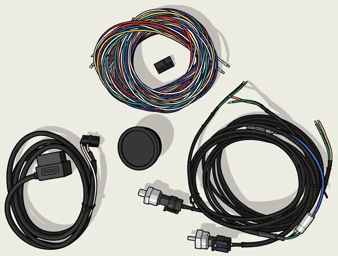
Revv Gauge, standard loom, and any sensors or extra cables -
Protective screen cover
Don’t be alarmed if the screen looks scratched — that’s just the plastic protective cover. It can be removed by taking off the bezel.
We recommend only removing the protective cover once installation is complete.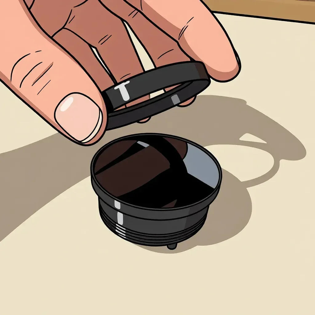
Remove the bezel 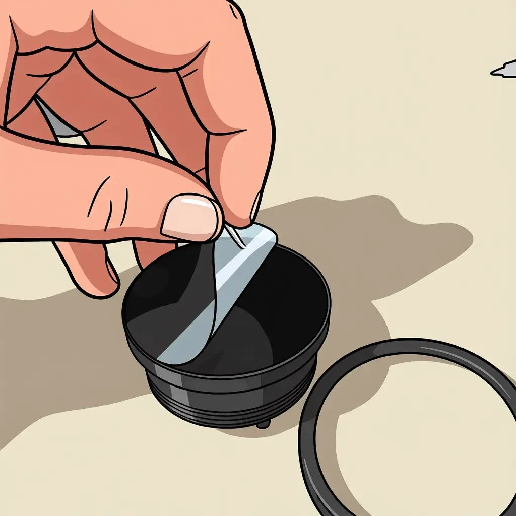
Peel off the plastic protective cover -
Choose your power connection
Are you using the standard loom or the OBD2 cable?
-
Insert cables into the Micro-Fit Molex
Every loom wire ends in a pre-crimped Micro-Fit terminal. These push into the back of the 16-pin Molex housing until they click and lock.
Hold the wire near the crimp and insert the metal terminal thin end first into the correct cavity. The terminal only seats one way — locking tabs must line up with the cavity. If it feels stuck, stop and check the orientation rather than forcing it.
Push firmly until you feel/hear a click. Give the wire a gentle tug to confirm it’s locked. Use this same method for power, ground, and every other input or output cable.
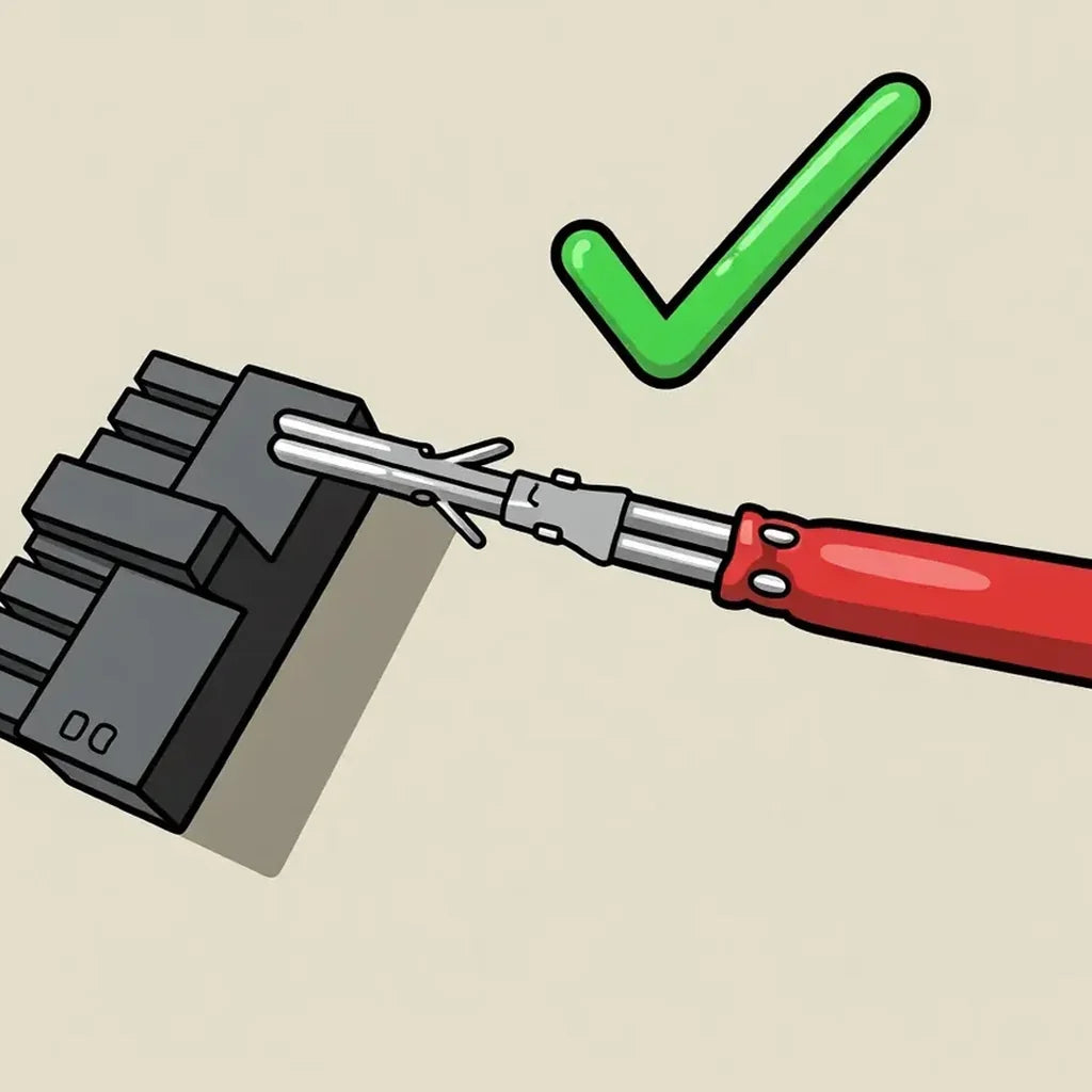
Correct — locking tabs aligned with the cavity 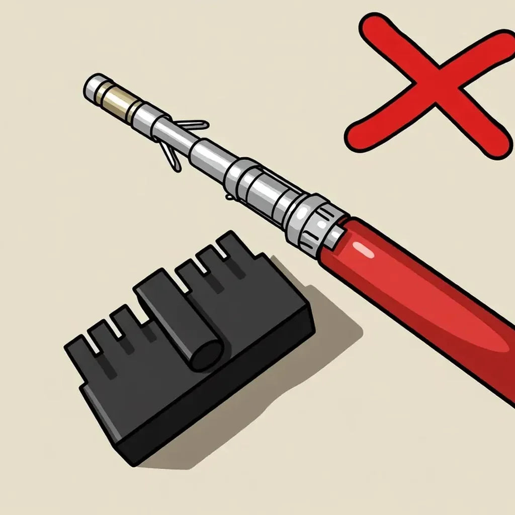
Incorrect — do not force a rotated terminal Insert the power cable
Insert the 12–24V power cable — VIN, red (RD), 18 AWG — into pin 13 on the 16-pin Molex.
Pay close attention when inserting: the pin must go in thin-end first, in this orientation.
Photo: power pin orientation into pin 13Pin 13 — VIN Red (RD) 18 AWG Insert the ground cable
Next, insert the GND cable — black (BK), 18 AWG — into pin 14. It splits into two so you can more easily run a ground to your analog sensors and a separate ground for the gauge power supply.
Photo: power and ground both insertedPin 14 — GND Black (BK) 18 AWG If you’re using the OBD2 cable, you can skip the power and ground pin steps — power is supplied from the OBD2 port. Use the insertion method above for any other pins you still need to seat.
-
Insert your other inputs
Decide which other inputs your gauge will need and insert those pins now. Tap the pin layout image to view it full screen for reference.
Insert your remaining wires into the Molex 16-pin Molex layout — tap to enlarge Insert the analog sensor wires into the matching Molex pins for your planned inputs. Keep sensor grounds tidy with the split GND lead from pin 14 if you’re on the standard loom.
- 9 AIN1 — Green (GN)
- 1 AIN2 — Brown (BN)
- 2 AIN3 — Grey (GY)
- 10 AIN4 — Yellow (YE)
- 3 AIN5 — Light green (LtGN)
- 4 AIN6 — White/Black (WHBK)
If you’re using linear 5V sensors, also insert +5V — orange (OG) — into pin 15 so those sensors are powered.
- 15 +5V — Orange (OG)
Insert the CAN high and CAN low wires into the Molex. There are two cavities for each so you can daisy-chain CAN if needed — confirm polarity before seating.
- 5 / 8 CAN H — White (WH)
- 6 / 7 CAN L — Blue (BU)
Insert the controllable output wires into the assigned output pins. Leave unused output pins empty until you need them.
- 11 DOUT1 — White/Brown (WHBN)
- 12 DOUT2 — White/Violet (WHVT)
Insert the LIGHT wire — white/grey (WHGY) — into pin 16. The other end connects to your vehicle’s illumination / headlight circuit so Revv Gauge can switch between light and dark themes when the lights turn on or off.
- 16 LIGHT — White/Grey (WHGY)
-
Move to your install location
You’re ready to move to where you’ll mount the gauge — car, tiny home, caravan, or elsewhere. Roughly route the wiring from the power source to the mount location.
Installing in a car? Pull the analog inputs, the +5V wire, and one of the GND wires through the firewall. That keeps fewer wires running through the dash. -
Wire in your device
With the loom prepared and wires roughly routed, you can begin wiring the gauge into your vehicle or setup. Open the sections that apply to your install.
Run each sensor signal wire to the matching analog input. Use a shared sensor ground from the split GND (pin 14), and power linear 5V sensors from +5V (pin 15).
- 9 AIN1 — Green (GN)
- 1 AIN2 — Brown (BN)
- 2 AIN3 — Grey (GY)
- 10 AIN4 — Yellow (YE)
- 3 AIN5 — Light green (LtGN)
- 4 AIN6 — White/Black (WHBK)
- 15 +5V — Orange (OG) — for linear 5V sensors
- 14 GND — Black (BK) — sensor ground
For NTC temperature sensors, connect signal to an AIN and the other leg to GND. For linear 0–5V sensors, connect signal to AIN, power to +5V, and ground to GND.
All REVV Gauge–issued sensor looms follow the same colours: 5V is orange, output / signal is green, and ground is black.
If you’re using all 6 inputs, plan how you’ll manage up to 6 ground wires and 6 +5V wires from the sensors — a bus bar or similar distribution block helps a lot. For 1–3 sensors, you can typically crimp the sensor grounds together onto the GND lead, and the sensor +5V wires together onto the +5V lead.
Connect CAN H and CAN L to your vehicle or ECU CAN bus. Keep polarity correct — white is CAN H, blue is CAN L. Pins 5/8 and 6/7 are paired so you can daisy-chain if needed.
When designing the gauge face in the app, you can enable the built-in 120 Ω termination if you need it — no need to terminate the bus manually.
- 5 / 8 CAN H — White (WH)
- 6 / 7 CAN L — Blue (BU)
These are low-side outputs. Connect the ground of the device you wish to toggle on and off here — for example a buzzer, LED, or relay — and power the device from a suitable supply.
Do not exceed 1W at 12V.
- 11 DOUT1 — White/Brown (WHBN)
- 12 DOUT2 — White/Violet (WHVT)
Leave unused outputs disconnected.
Connect the LIGHT wire to your vehicle’s illumination or headlight circuit so the gauge can switch themes when the lights turn on or off.
- 16 LIGHT — White/Grey (WHGY)
Plug the OBD2 connector into the vehicle’s OBD2 port. On most cars this is under the driver’s footwell, near the kick panel or steering column.
It’s normal for the gauge to boot even with the car off — the OBD2 port is connected directly to battery. Once you load a gauge onto the device, you can set it to auto sleep. If you follow the setup in the app, this is configured automatically for OBD2.
If you’re on the standard loom, connect VIN to a fused 12–24V supply and GND to chassis / battery negative.
In a vehicle, use an ignition-switched circuit so the gauge is powered when the vehicle is on — not a permanent battery feed (unless you want it always on).
- 13 VIN — Red (RD) 18 AWG
- 14 GND — Black (BK) 18 AWG
OBD2 installs can skip this — power and ground come from the OBD2 port.
-
Mount the device
Mount the gauge in your chosen location. If you’re using a gauge pod or similar, it’s recommended to wrap some electrical tape around the body to increase the diameter until it’s a tight fit.
The gauge uses an M52×2 thread. Print the lock ring STEP to help secure the device, or download the case STEP if you want to design your own gauge pod.
-
Download the app
Download REVV Editor, then follow the in-app instructions to connect your gauge, load a layout, and finish setup.
